The UTL-X IDE
While the CLI is powerful for quick transformations and scripting, professional integration development happens in an IDE. UTL-X provides a VS Code extension backed by the utlxd daemon, giving you real-time feedback, autocompletion, and live preview as you write transformations.
This chapter describes the IDE experience and its two modes: IDE Runtime and IDE Design Time. If you're using UTL-X purely from the command line, you can skip ahead to Chapter 8 — but the IDE will make you significantly more productive.
Installing the VS Code Extension
The UTL-X extension is available from the VS Code marketplace:
Open VS Code
Go to Extensions (Ctrl+Shift+X / Cmd+Shift+X)
Search for "UTL-X"
Click Install
The extension automatically starts the utlxd daemon when you open a .utlx file. No manual configuration needed — the daemon manages its own lifecycle.
Two Modes: IDE Runtime and IDE Design Time
The IDE operates in two distinct modes, each serving a different workflow:
IDE Runtime
IDE Runtime is the IDE's default mode — a graphical overlay on top of the UTL-X CLI. It provides:
A three-panel layout: Input, Transformation, Output
Syntax highlighting, autocompletion, and real-time error diagnostics
Live preview: as you type, the transformation runs against sample input and shows the result
The function library browser for all 650+ stdlib functions
The UDM tree browser showing parsed input structure
In IDE Runtime, you experiment. You paste sample data, write a .utlx transformation, and see the output instantly. There is no schema awareness — you work with the data as-is, guided by the live preview. This is how you prototype transformations, explore unfamiliar data structures, and iterate quickly.
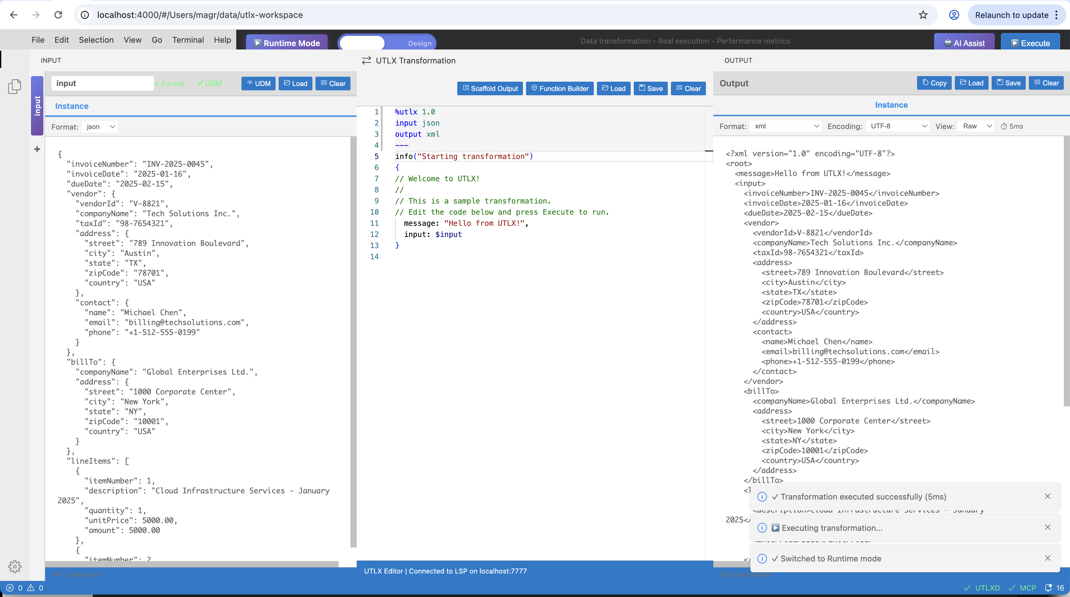
IDE Runtime — JSON input (left), UTL-X transformation (center), XML output (right). The blue "Runtime Mode" badge indicates IDE Runtime is active.
IDE Runtime is essentially the CLI with a GUI on top. The utlxd daemon runs the same parser and interpreter as utlx, but does so on every keystroke and pipes the result to the output panel.
IDE Design Time
IDE Design Time is for professional schema-driven development. The key difference: both the input schema and output schema are known in advance. Your job is to write the .utlx that bridges the gap between them.
This distinction is fundamental and worth understanding clearly, because it is easy to confuse what the IDE shows at design-time with what UTL-X processes at runtime.
What happens at runtime
At runtime — whether in the CLI, IDE Runtime, or the UTLXe production engine — UTL-X processes instance documents. An instance document is a concrete message: a specific JSON object, a specific XML file, a specific CSV with actual rows of data. These are always Tier 1 formats (JSON, XML, CSV, YAML). The .utlx transformation receives an instance document as $input and produces an instance document as output.
%utlx 1.0
input json          // ← receives a JSON instance document
output xml          // ← produces an XML instance document
---
// $input is a concrete JSON object like {"orderId": "ORD-42", "total": 299.99}
This is true even when you are transforming data that conforms to a schema. The schema is not the input — the instance is.
What happens at design-time
At design-time, the IDE adds a layer above the instance level. You provide the schemas that describe the input and output contracts — an XSD, a JSON Schema, an Avro schema, a Protobuf definition. The IDE uses these schemas to show you the structure of the data: what fields exist, what types they have, which are required, what constraints apply.
This is the schema-to-schema perspective. The IDE displays the input schema structure on the left and the output schema structure on the right. Your job is to write the .utlx transformation that maps from one to the other.
Input Schema                     .utlx Transformation              Output Schema
─────────────                    ─────────────────────              ─────────────
JSON Schema:                     %utlx 1.0                         XSD:
{                                input json                         <xs:element name="Order">
  "orderId": string (required)   output xml                           <xs:element name="id"
  "customer": {                  ---                                     type="xs:string"/>
    "name": string               <Order>                              <xs:element name="customer"
    "email": string                <id>{$input.orderId}</id>              type="xs:string"/>
  }                                <customer>                         <xs:element name="total"
  "total": number                    {$input.customer.name}              type="xs:decimal"/>
}                                  </customer>                      </xs:element>
                                   <total>{$input.total}</total>
                                 </Order>
But here is the critical point: the schema is not the runtime input. When this transformation runs in production, $input will not contain a JSON Schema — it will contain a concrete JSON object like {"orderId": "ORD-42", "customer": {"name": "Alice"}, "total": 299.99}. The schemas are a design-time aid that the IDE uses to guide you; they are never passed to the transformation engine.
Why this distinction matters
Consider a common enterprise scenario: you need to transform purchase orders from a supplier's JSON API into UBL XML invoices for your ERP system.
Without IDE Design Time (IDE Runtime only):
You paste a sample JSON purchase order in the input panel
You write the transformation by trial and error
You have no way of knowing if your XML output is valid UBL — you are guessing at the target structure
If the supplier adds a new field next month, you won't know about it until a message fails
With IDE Design Time:
You load the supplier's JSON Schema (from their API documentation) as the input schema
You load the UBL XSD as the output schema
The IDE shows you every field on both sides: what's required, what's optional, what types are expected
As you map fields, the IDE validates that your output conforms to UBL — missing required elements are flagged immediately
Completeness tracking shows which target fields you haven't mapped yet
The schemas make the transformation provably correct before a single production message flows through it.
Tier 1 vs Tier 2: which mode applies
IDE Design Time is exclusively for Tier 1 to Tier 1 mapping — transforming instance documents (JSON, XML, CSV, YAML) while using schemas as structural guides. The schemas help you build the transformation but are not the runtime input or output.
The moment either the input or output is a Tier 2 format (a schema itself — XSD, JSON Schema, Avro, Protobuf, OData Schema, Table Schema), only IDE Runtime applies. You are no longer mapping instances guided by schemas — you are processing schemas as data. This is a fundamentally different operation.
UTL-X supports all four combinations:
| Input | Output | Mode | Example |
| Tier 1 | Tier 1 | IDE Design Time or IDE Runtime | JSON purchase order → XML UBL invoice |
| Tier 1 | Tier 2 | IDE Runtime only | CSV spreadsheet with field definitions → XSD schema generation |
| Tier 2 | Tier 1 | IDE Runtime only | Extract type names and field counts from an XSD → JSON report |
| Tier 2 | Tier 2 | IDE Runtime only | Convert Avro schema → Protobuf definition (Chapter 28) |
Tier 1 → Tier 1 (IDE Design Time or IDE Runtime): The most common case. A JSON message arrives, you transform it to XML. Both sides are instance documents. In IDE Design Time, schemas guide you. In IDE Runtime, you work directly with sample data. Either mode works.
Tier 1 → Tier 2 (IDE Runtime only): The input is an instance document, but the output is a schema. For example: a CSV spreadsheet describing database columns (field name, type, nullable) is transformed into an XSD or JSON Schema. The CSV is Tier 1 data; the output is a Tier 2 schema. There is no "output schema" for the IDE to validate against — the output IS a schema. Only IDE Runtime makes sense.
%utlx 1.0
input csv                // Tier 1: spreadsheet with column definitions
output xsd               // Tier 2: generate an XSD from the metadata
---
// $input is CSV rows like: name,type,required
//                          orderId,string,true
//                          total,decimal,true
$input
Tier 2 → Tier 1 (IDE Runtime only): The input is a schema, and you extract information from it into a regular data format. For example: read an XSD schema and produce a JSON report listing all type names, field counts, and constraints. The XSD is parsed as data (Tier 2 input); the output is a plain JSON document (Tier 1). No IDE Design Time schema-to-schema perspective applies — the input IS a schema.
%utlx 1.0
input xsd                // Tier 2: an XSD schema as input
output json              // Tier 1: extract schema metadata as JSON
---
{
  typeCount: count(keys($input["%types"])),
  types: keys($input["%types"])
}
Tier 2 → Tier 2 (IDE Runtime only): Schema-to-schema conversion — the input is a schema in one format and the output is a schema in another. See Chapter 28 for full coverage.
%utlx 1.0
input xsd                // Tier 2: XSD schema
output jsch              // Tier 2: convert to JSON Schema
---
$input
Summary: IDE Design Time vs IDE Runtime
| Concept | IDE Design Time | IDE Runtime |
| Input | Schema as structural guide | Instance document or schema as data |
| Output | Schema as validation target | Instance document or schema as data |
| Applicable formats | Tier 1 → Tier 1 only | Any combination (T1→T1, T1→T2, T2→T1, T2→T2) |
| Purpose | Guide the developer, validate correctness | Execute transformation against sample data |
$input | Sample data (for live preview) | Sample data or schema as data |
| Schemas | Displayed as structural guides | Not used |
What IDE Design Time provides
Schema-to-schema perspective: the input and output structures are displayed side-by-side, derived from their schemas (XSD, JSON Schema, Avro, Protobuf, Table Schema, OData Schema)
Output validation: the IDE checks your transformation output against the declared output schema in real-time
Completeness tracking: unmapped target fields are flagged — you can see at a glance which parts of the output contract are not yet covered
Scaffolding: the IDE can generate a transformation skeleton with all target fields, placeholder expressions, and TODO comments for fields requiring business logic
Type checking: source-to-target type mismatches are highlighted (e.g., mapping a string where an integer is expected)
This is how Tibco BW, SAP CPI, and MuleSoft approach mapping — define the contracts first, then build the transformation. UTL-X does this for all schema formats, not just XML/XSD.
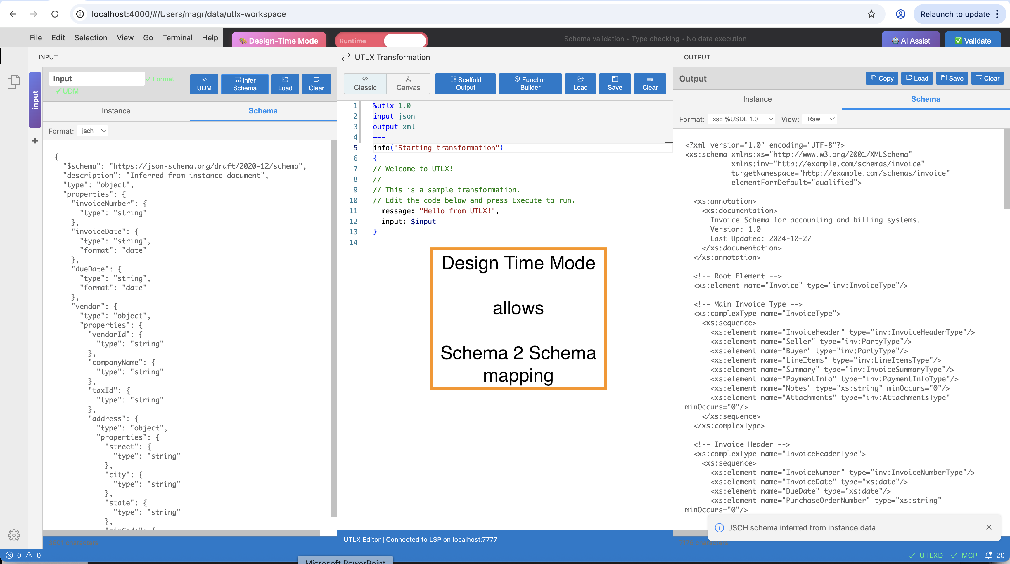
IDE Design Time — JSON Schema on the input side (left), inferred output schema (right). The green "Design Time Mode" badge indicates IDE Design Time is active. The schemas guide the developer; at runtime, $input receives instance documents, not schemas.
When to Use Which Mode
| Scenario | Mode | Why |
| Exploring unfamiliar data | IDE Runtime | No schema yet — discover the structure first |
| Quick format conversion | IDE Runtime | Paste input, write mapping, done |
| Enterprise integration project | IDE Design Time | Contracts are known — validate against them |
| Building a mapping between two APIs | IDE Design Time | Both schemas available from OpenAPI/XSD |
| Debugging a failing transformation | IDE Runtime | Paste the failing message, see what happens |
| Handoff to production (utlxe) | IDE Design Time | Ensures output matches the production contract |
The Three-Panel Layout
Both modes share the same visual layout:
Left panel — Input: paste or load sample input data (IDE Runtime) or display the input schema structure (IDE Design Time). Select the format (XML, JSON, CSV, YAML, OData).
Center panel — Transformation: the .utlx editor with syntax highlighting, autocompletion, and real-time error diagnostics. This is where you write your transformation logic.
Right panel — Output: the live preview of the transformation result (IDE Runtime) or the expected output schema with validation status (IDE Design Time).
The IDE vs UTLXe
The IDE and the UTLXe production engine serve different purposes — they are not the same runtime:
| Aspect | IDE (utlxd) | Production Engine (utlxe) |
| Purpose | Develop and test .utlx files | Execute .utlx files at scale |
| Input | Sample data pasted by developer | Live messages from Kafka, HTTP, file system |
| Concurrency | Single transformation at a time | 8–128 workers processing in parallel |
| Validation | Optional schema check in IDE Design Time | Enforced schema validation per pipeline config |
| Output | Displayed in output panel | Routed to target system (API, queue, file) |
| Metrics | None | Prometheus counters, histograms, health probes |
| Lifecycle | Starts/stops with VS Code | Long-running daemon or container |
The .utlx file is the common artifact. You create it in the IDE, test it with sample data, validate it against schemas — then deploy it unchanged to utlxe. No compilation, no packaging, no build step. The source IS the production artifact.
See Chapter 32 for the UTLXe engine lifecycle, Chapter 33 for cloud deployment, and Chapter 19 for the production engine header and configuration.
The UDM Tree Browser
The UDM tree browser is a panel that shows the parsed Universal Data Model as an interactive tree. Load sample data in the input panel, and the tree browser displays the complete structure:
Each node in the tree shows:
Property name: the field name in the data
UDM type: Scalar, Object, Array, DateTime, etc.
Value: for scalar nodes, the actual value
Format-specific information:
XML: element name, attributes (@attr), namespace declarations
JSON: type (string, number, boolean, null, object, array)
CSV: column index, header name, detected type
YAML: anchor/alias references
OData: @odata.type, navigation properties
Click a node to insert the accessor path into the transformation editor. For example, clicking the "Name" node under "Customer" inserts $input.Customer.Name at the cursor position. This eliminates typos and speeds up field mapping.
The Function Library
The function library panel lets you browse all 650+ standard library functions without leaving the editor:
Browse by category: 18 categories (String, Array, Math, Date, Type, Encoding, XML, JSON, CSV, YAML, Security, Binary, Financial, Geospatial, Utility, Object, Core, Other)
Search: type a keyword to find functions by name or description
Function details: name, signature (parameter types and return type), description, example
Click to insert: click a function name to insert a call template at the cursor
For example, searching "date" shows: now(), today(), parseDate(), formatDate(), addDays(), diffDays(), and more — with signatures and examples for each.
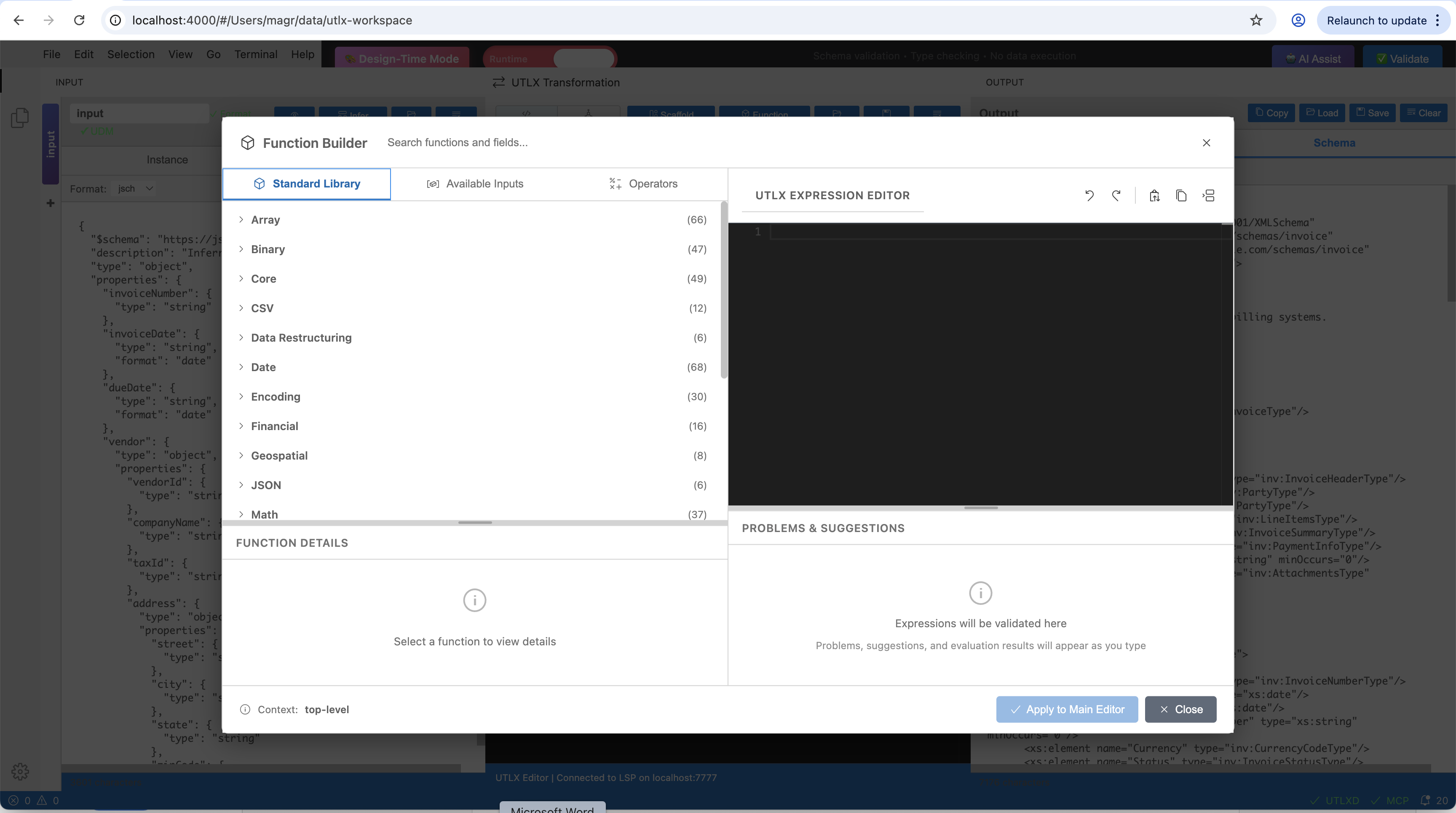
The Function Builder — Standard Library tab showing all 18 function categories with counts. Select a category to browse functions, view signatures, and insert them into the editor.
The Function Builder has three tabs:
Standard Library: browse all 650+ functions by category
Available Inputs: shows the fields available from
$inputwith their detected types — useful for exploring unfamiliar data structures without switching to the tree browserOperators: browse all UTL-X operators (logical, pipe, safe navigation, nullish coalescing, lambda arrow, spread) with descriptions
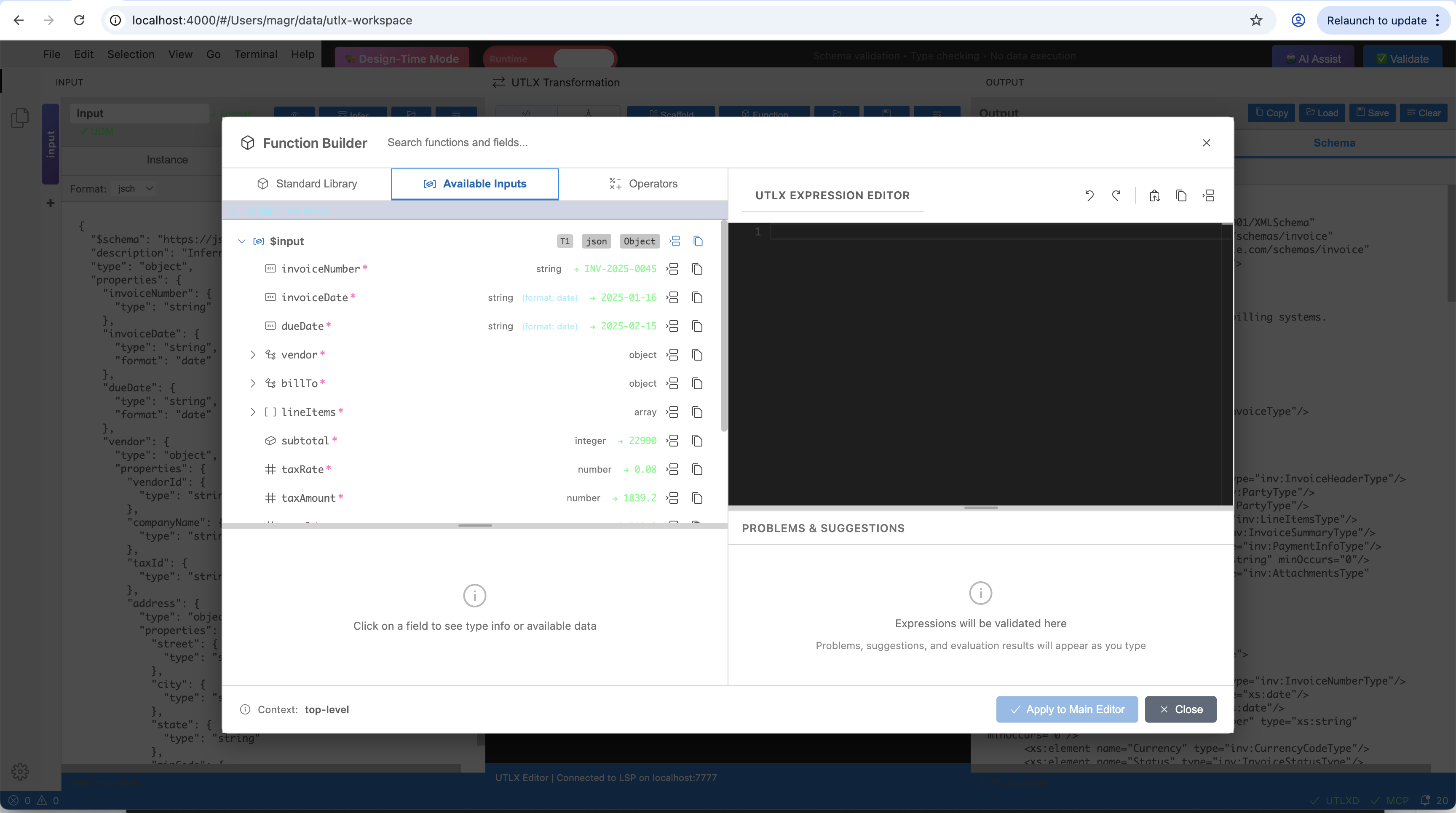
Available Inputs tab — shows input fields with their detected types (array, string, number, integer). Click a field to insert its accessor path.
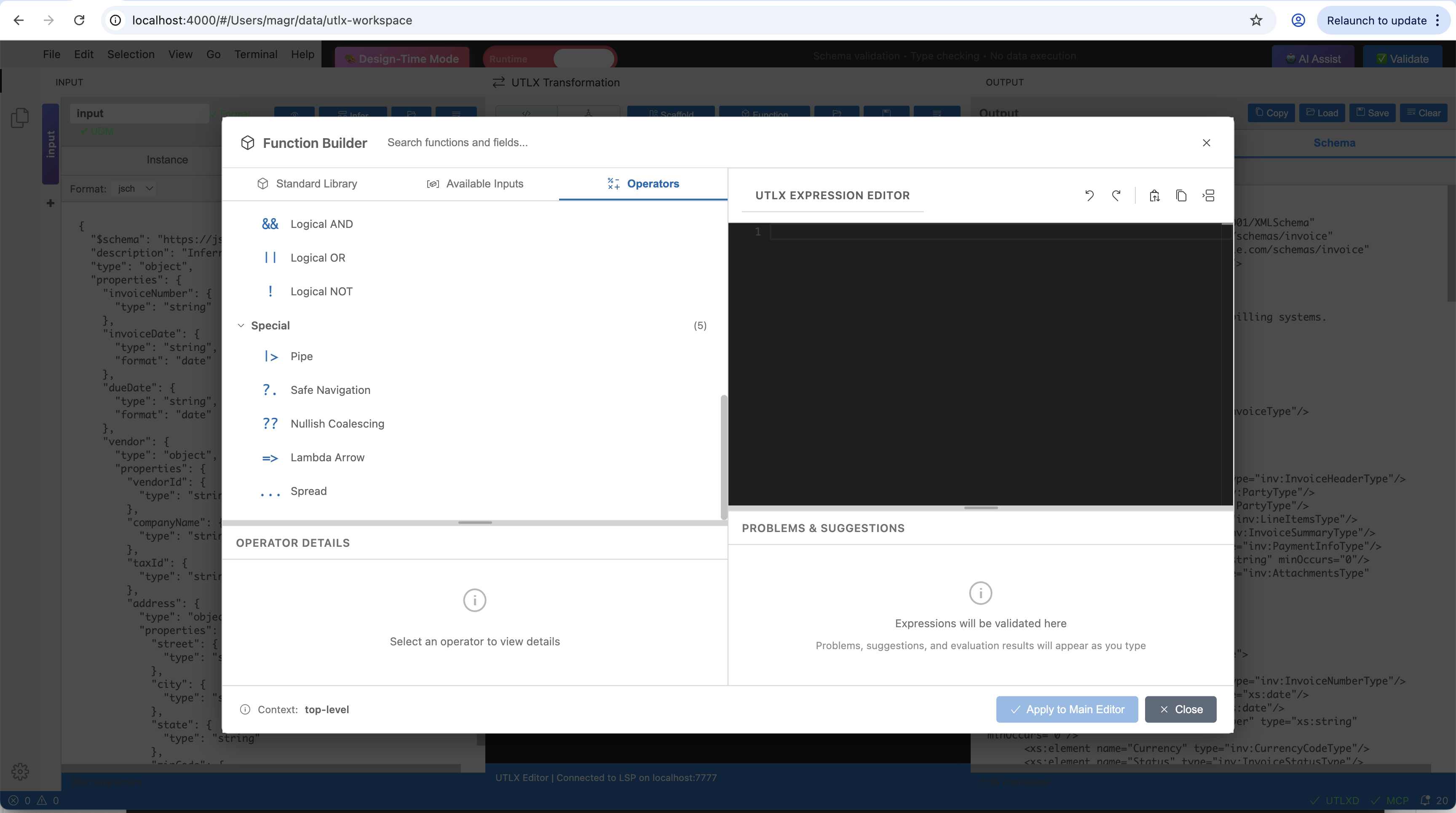
Operators tab — browse logical operators, pipe, safe navigation, nullish coalescing, lambda arrow, and spread with descriptions.
Real-Time Diagnostics
The IDE shows errors as you type, without saving or running:
Syntax errors: missing brackets, invalid keywords, unterminated strings — highlighted with red underlines and error messages
Unknown functions: calling a function that doesn't exist in the stdlib — immediately flagged
Type warnings: passing a string where a number is expected (when detectable from context)
Schema violations: (IDE Design Time) when output doesn't match the declared output schema
Errors appear in the Problems panel (Ctrl+Shift+M) with line numbers and descriptions. Click an error to jump to the offending line.
Autocompletion
The IDE provides context-aware autocompletion:
After
$input.: property names from the parsed input data (IDE Runtime) or from the input schema (IDE Design Time)After a function name and parenthesis: parameter hints showing expected types
At the start of an expression: function names, keywords (
if,let,match,try)Inside an object literal: available property names from the output schema (IDE Design Time)
Autocompletion uses the utlxd daemon's real-time understanding of your transformation — it's not a static word list but a live analysis of the AST and available data.
The Header Editor
The .utlx header (the part above the --- separator) can be edited visually:
Input format: dropdown to select XML, JSON, CSV, YAML, OData
Output format: dropdown with format-specific options
Output options: checkboxes and fields for options like
writeAttributes,encoding,delimiterMulti-input: add or remove named inputs with their formats
Schema references: attach input and output validation schemas (IDE Design Time)
The header editor generates the header block — you can always switch to text editing if you prefer manual control.
Keyboard Shortcuts
| Shortcut | Action |
| Ctrl+Space | Trigger autocompletion |
| F12 | Go to definition |
| Shift+F12 | Find all references |
| Ctrl+Shift+F | Format document |
| Ctrl+Shift+M | Show Problems panel |
| Ctrl+K Ctrl+I | Show hover information |
| Ctrl+Shift+P then "UTL-X" | All UTL-X commands |
Tips for Productive IDE Usage
Start with sample data. Before writing a single line of transformation code, paste representative sample data in the input panel. The UDM tree browser and autocompletion become dramatically more useful when they have real data to analyze.
Use the live preview. Don't run transformations from the terminal during development. The live preview updates on every keystroke — you see the output change as you type. This is faster than any save-compile-run cycle.
Work schema-first when schemas exist. If you have schemas for both input and output, switch to IDE Design Time and load them. The IDE validates your output in real-time, catching contract violations before you even save the file.
Browse functions, don't memorize. With 650+ functions, nobody remembers them all. Use the function library search. Type what you want to do — "convert date", "filter array", "encrypt" — and the library shows relevant functions.
Trust the red underlines. If the IDE shows an error, fix it before moving on. Real-time diagnostics catch 90% of issues that would otherwise only surface at runtime.